WOODEN PATCHBOX LID:
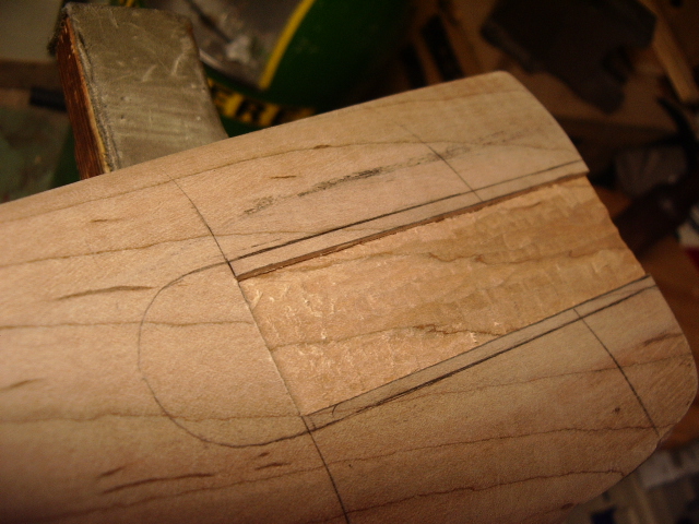
Using the Golden Means method, I used the divider across the lock panel (5) then flipped the dividers and measured the short side 3) from the front of the lock toward the rear of the lock. Then I measured another short (3) toward the wrist. Made a mark and then I measured the (5) distance to the end of the buttplate. Rotated the dividers and from the wrist measured the (3) distance. The showed me where the end of the patchbox lid should be. Since this is a 16" pull, I wanted it to be in perspective.
With the template positioned and parallel to
the belly, I traced a line around the template. To aid in repositioning the
template each time, I drew two lines across the template and onto the stock. 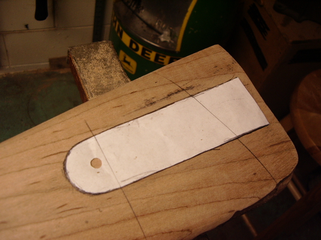 (For
more information or additional notes, see Wood
Patchbox Installation in Tips & Aids section.)
(For
more information or additional notes, see Wood
Patchbox Installation in Tips & Aids section.)
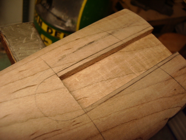
The next step was to flatten the surface with
files. Then I used a straight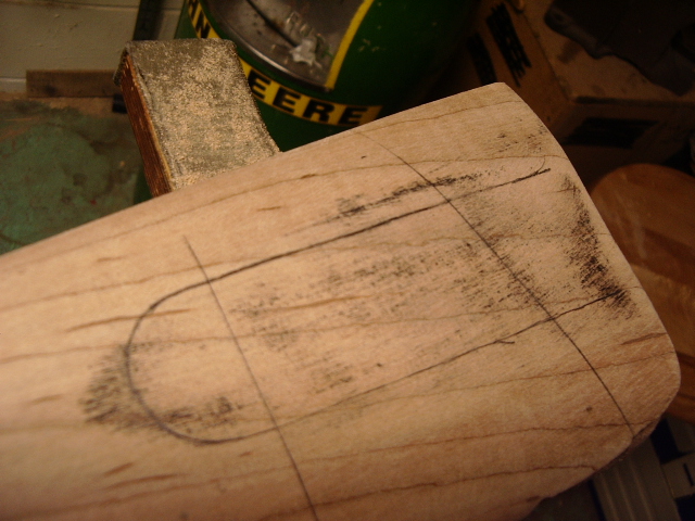 edge to identify the high spots.
Kept this up until I had black marks evenly across the face of the stock.
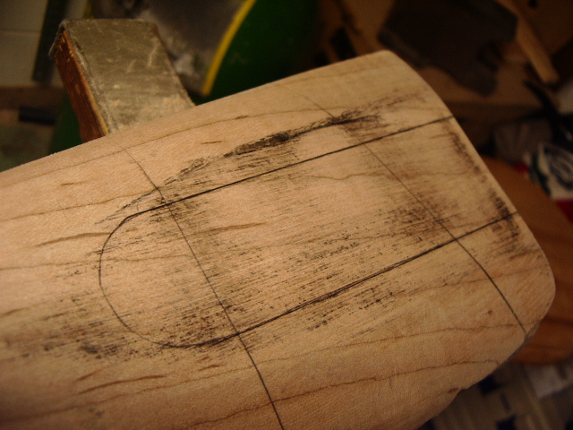
Then I smoothed the surface down with sand paper. Measured in 1/8" along each side of the lid and chiseled out this area to a depth of 1/4". I used a depth gauge to monitor for any high spots.
 I
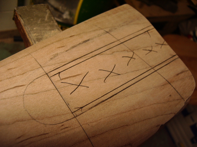
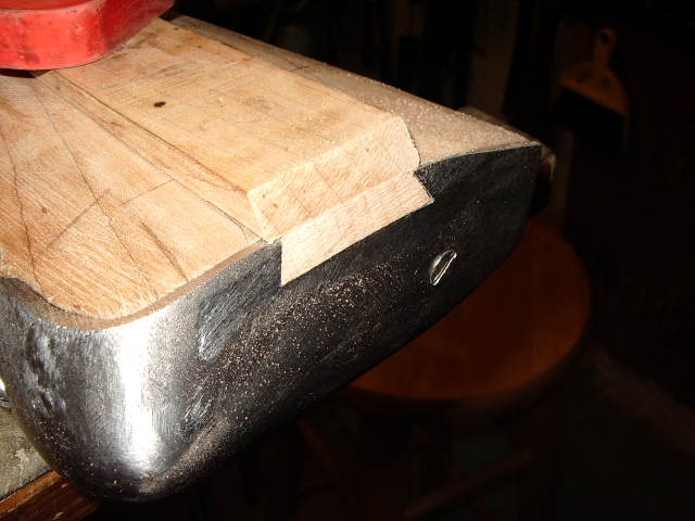
also made two 60 degree marks on the end of the stock for the dovetails. This
served as a guide for me when I used my knife to cut inward to remove wood. Then
I followed up with a triangular safe file to clean up the dovetails.
I
also made two 60 degree marks on the end of the stock for the dovetails. This
served as a guide for me when I used my knife to cut inward to remove wood. Then
I followed up with a triangular safe file to clean up the dovetails. 
Next I measured and cut out the base for the lid. (For more information or additional notes, see Wood Patchbox Installation in Tips & Aids section.)
To install this I used carbon paper as I
carefully drove the base into the dovetails. This left real nice marks on the
sides of the base so I could remove them. 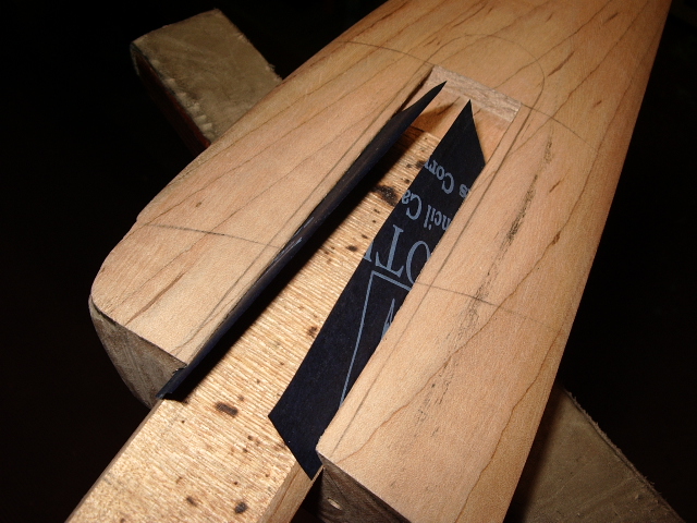
 I
continued this until the base was fully inlet into the stock cavity.
I
continued this until the base was fully inlet into the stock cavity.
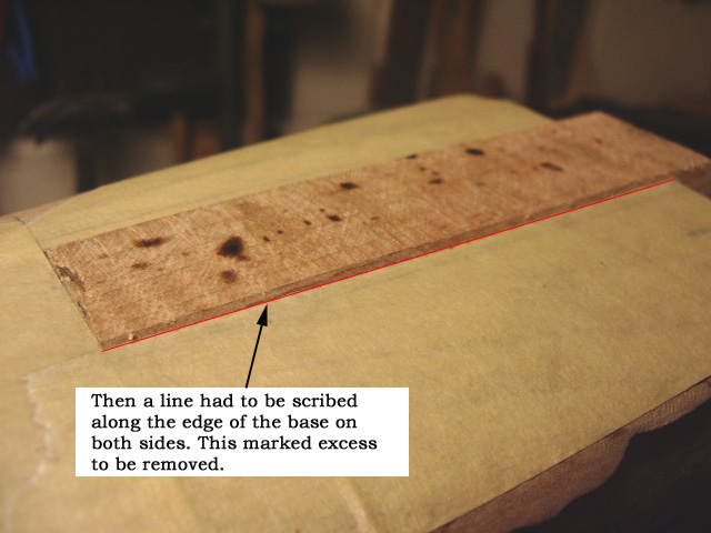 Now
I had to mark a scribed line on either side of the base. The
Now
I had to mark a scribed line on either side of the base. The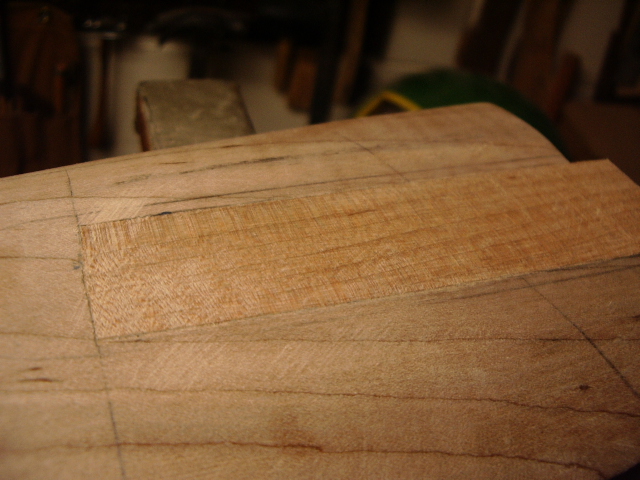 wood above the line was excess wood. Once down to the line, flatten it and use a
straight edge tool again.
wood above the line was excess wood. Once down to the line, flatten it and use a
straight edge tool again.
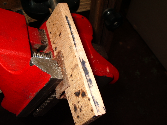
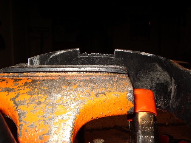
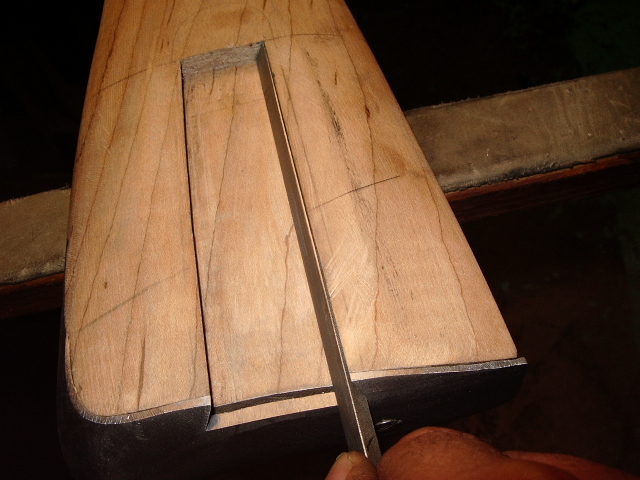
With the base inlet and
flattened, I needed to put the dovetails into the buttplate. The buttplate
was remounted and a line was inscribed on the inside. Using a hacksaw, I cut
down close to the line and remove the metal in the slotted area. 
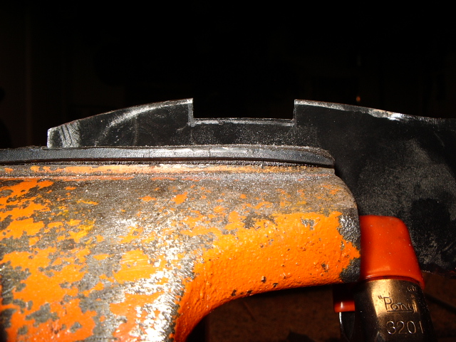
I then remounted the buttplate
onto the stock and put some masking tape inside the base cavity. This protects
the surface when filing the metal on the base down to the same level as the
bottom of the cavity. 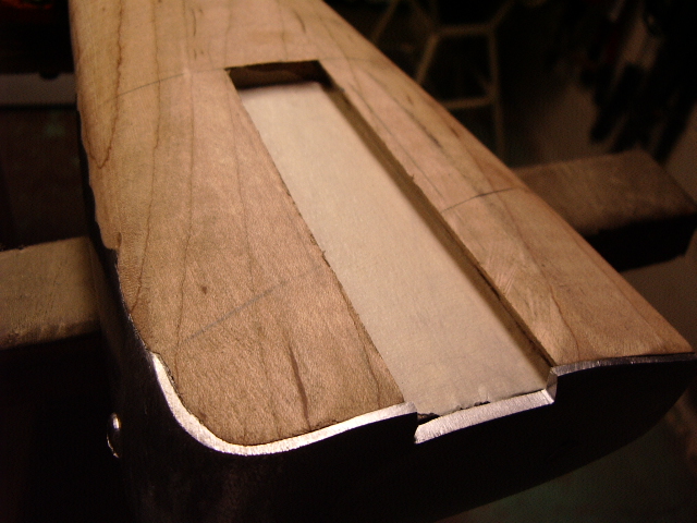
Using a triangular safe file I cut into each dovetail.
Then I inserted the base and
altered between filing the buttplate and removal of wood from the base that had
not been inlet into the dovetail yet. Finally the base was fully inlet. 
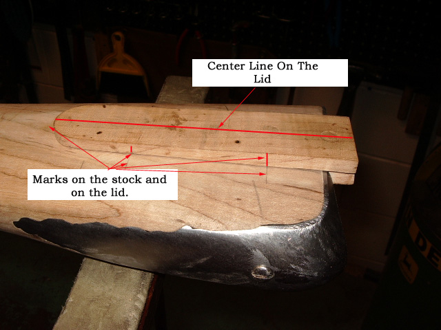
I have already cut out the wooden lid and have to make sure the base is flattened better, as you can see one edge is still a little high. Having cleaned up the lid. I drew two intersecting lines across the stock and the base. I then laid the lid into position and then marked where the intersecting lines met the lid along the sides.
This allowed me to make sure the
two halves were properly aligned prior to gluing them together. The two halves
were then epoxied together. 
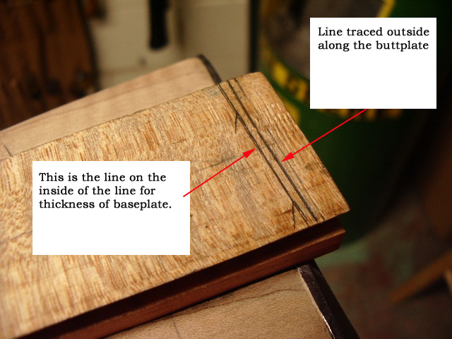 With
the lid in place, I drew a line under the base along the buttplate. Then I
pulled it out and marked out a line 1/16" inside of this line. This will be
the thickness of the lid base. Next I cut off the excess wood on the
outside of the outside traced line. This removed a lot of excess wood making it
easier to file the end flush with the buttplate.
With
the lid in place, I drew a line under the base along the buttplate. Then I
pulled it out and marked out a line 1/16" inside of this line. This will be
the thickness of the lid base. Next I cut off the excess wood on the
outside of the outside traced line. This removed a lot of excess wood making it
easier to file the end flush with the buttplate.
Then
I put the lid back into the dovetails and aligned the inside lin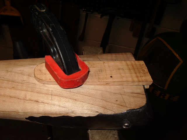 e
with the edge of the buttplate. The lid was clamped into this position and
using files, the surface of the end of the lid was filed flush with the the
buttplate.
e
with the edge of the buttplate. The lid was clamped into this position and
using files, the surface of the end of the lid was filed flush with the the
buttplate.
When finished filing, slide the
lid fully into place and you will 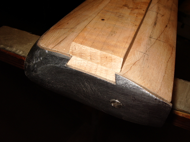 see
the thickness of the base plate is now exposed.
see
the thickness of the base plate is now exposed.
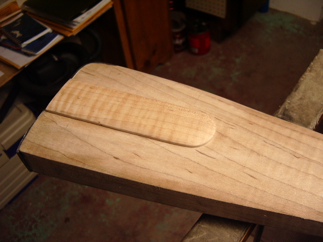
Then I
removed the lid and drew a 1/16" line around the perimeter. Measured height
of the rear portion of the lid to be 5/16" and the front to 1/8". Drew
a diagonal line along both sides. Then I filed the lid flat to this line,
resulting in a tapering lid toward 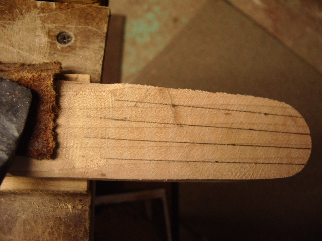 the
front. Then I divided the the width of the lid into 5 sections. Using my
4-N-One hand file, I rounded the top surface of the lid.
the
front. Then I divided the the width of the lid into 5 sections. Using my
4-N-One hand file, I rounded the top surface of the lid.


To make the base, I found some scrap steel 1/16" thick in the shop. Laid it against the base of the lid and traced around the end of the lid. Cut out the steel 1/4" away from the lines around the perimeter. Then I measured in 3/16" in from each side of the patchbox lid for the mounting screws. I used two no. 4 screws that were 3/8" long. I put punch marks were I wanted the pilot hole to be. Measured and located similar marks on the the metal base. (I made sure the lower edge of the base was at leaset 1/16" below the bottom of the lid. Due to the angle, I wanted to make sure I had enough metal to remove for a flat surface here.)
I
drilled the two pilot holes thru the metal and aligned these holes with the
punch marks in the lid. Once aligned, I drilled the two 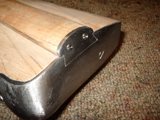 pilot
holes into the lid thru the metal base. Clearance holes were drilled thru the
base for the screws and the base was screwed to the lid. With careful
filing, the excess metal as filed away down to the lid. Next to allow the
lid to fit properly into the base, I used typewriter carbon paper to make the
lid base for any final filing. Here is the result.
pilot
holes into the lid thru the metal base. Clearance holes were drilled thru the
base for the screws and the base was screwed to the lid. With careful
filing, the excess metal as filed away down to the lid. Next to allow the
lid to fit properly into the base, I used typewriter carbon paper to make the
lid base for any final filing. Here is the result.
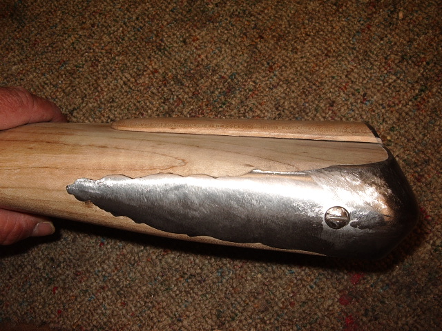
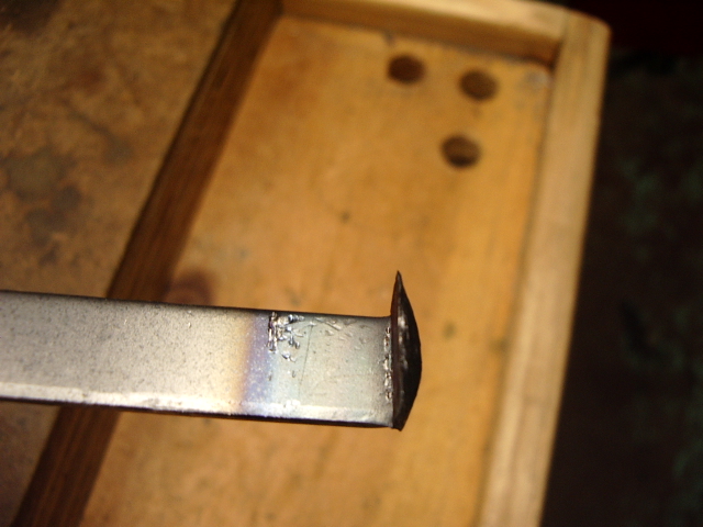
Now have started working on the lid latch spring. The end of the spring was heated and peened into shape. Next the spring will be peened over to match the angle of the base, then peened to taper thickness and shaped for inletting.

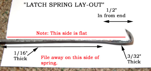 With
the button formed, I then measured out the approximate length of the latch
spring to be 2-1/2" long. From the button end, I measured in 1/2" and
made a line across the spring. This is the area that will remain the 3/32"
thick. The remainder of the spring length was taken down to 1/16".
Note; I took down the side that will be exposed and left the inlet side flat.
With
the button formed, I then measured out the approximate length of the latch
spring to be 2-1/2" long. From the button end, I measured in 1/2" and
made a line across the spring. This is the area that will remain the 3/32"
thick. The remainder of the spring length was taken down to 1/16".
Note; I took down the side that will be exposed and left the inlet side flat.

With the spring thinned down, I traced out the pattern for the spring onto the spring steel. Identified where the screw hole was to be located. I used files to take down the sides and shape the end of the spring.
 Once
this was done, I flattened the backside of the button and then cut in flat edges
on either side of the button. This will conceal the recess slot I will make in
the base after the spring is inlet.
Once
this was done, I flattened the backside of the button and then cut in flat edges
on either side of the button. This will conceal the recess slot I will make in
the base after the spring is inlet.
Then
I laid the latch spring into the final position, making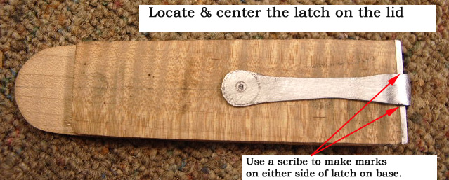 sure the button on centrally located the screw was centered in the lid. I
used a knife to scribe marks on either side of the latch to identify exactly
where the spring will pass thru the base plate.
sure the button on centrally located the screw was centered in the lid. I
used a knife to scribe marks on either side of the latch to identify exactly
where the spring will pass thru the base plate.
I
drilled a 1/16" pilot hole thru the end of the spring. Then I determined
how deep the screw recess was going to be into the 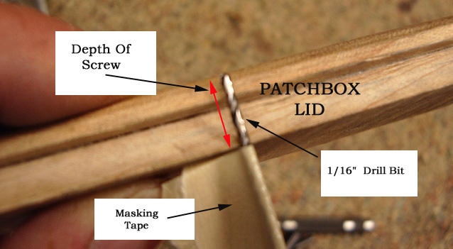 lid
without coming out the other side. Holding a drill bit up
lid
without coming out the other side. Holding a drill bit up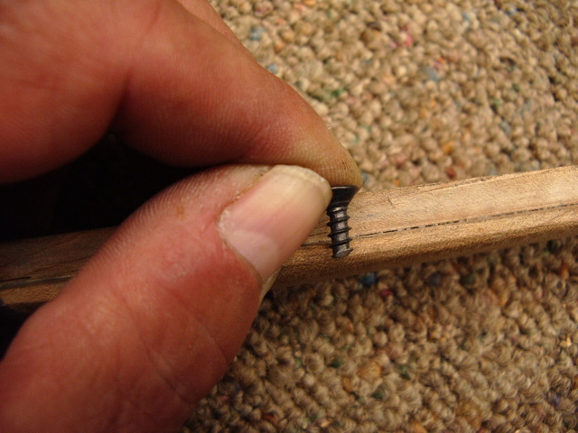 against the side of the lid, I put masking tape on the bit to serve as a stop
for the drill bit. Then I ground a screw to the depth I needed.
against the side of the lid, I put masking tape on the bit to serve as a stop
for the drill bit. Then I ground a screw to the depth I needed.
Next I drilled a bevel into the spring for the screw to be flush. Mounted the spring to the lid and clamped it into position. With a knife I made the initial cut around the spring to start inletting it into the lid.
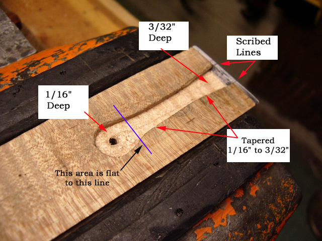 NOTE:
The inletted the area around the screw area was flat to the line in the
photo. This will serve as the fulcrum for the spring. From the line to the end
of the inlet area toward the base, it was tapered from 1/16" to 3/32"
at the base. Next I scribed a line inside of the base plate in the inletted
area. This provided me a guide line to follow. Using flat 'safe' file, I filed
down thru the base plate to the wood and then to each side carefully. Then I
laid the spring into the recessed area and kept removing excess wood until the
spring was flush to the wood in the 3/32" area of the inletted area. Now I
know the spring will compress far enough for it to latch properly later.
NOTE:
The inletted the area around the screw area was flat to the line in the
photo. This will serve as the fulcrum for the spring. From the line to the end
of the inlet area toward the base, it was tapered from 1/16" to 3/32"
at the base. Next I scribed a line inside of the base plate in the inletted
area. This provided me a guide line to follow. Using flat 'safe' file, I filed
down thru the base plate to the wood and then to each side carefully. Then I
laid the spring into the recessed area and kept removing excess wood until the
spring was flush to the wood in the 3/32" area of the inletted area. Now I
know the spring will compress far enough for it to latch properly later.
With
the latch spring now fully inletted into the lid and thru the base, I needed to
identify in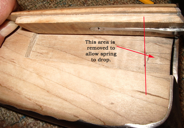 the stock cavity where to relieve wood to allow the spring to latch onto the
buttplate. To do this I laid the lid into the stock; drew lines where the spring
starts to protrude from the lid and removed the wood in this area.
the stock cavity where to relieve wood to allow the spring to latch onto the
buttplate. To do this I laid the lid into the stock; drew lines where the spring
starts to protrude from the lid and removed the wood in this area.
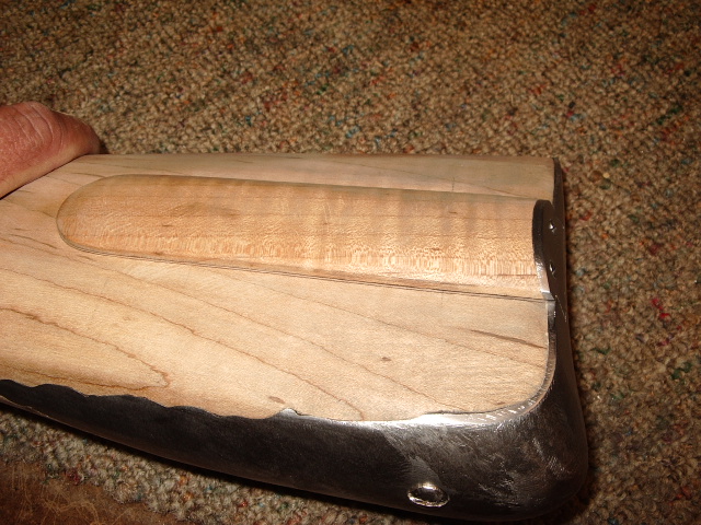
Having
done this, I slid the lid into the stock fully, then scribed a line across the
exposed spring along the edge of the buttplate. This marked the outside edge of
the latch. Removed the latch. Using calibers I measured the thickness of the
buttplate at the top and the bottom areas the latch will make contact. (You can
see this may vary on the thickness of the buttplate.)  Transferred
this measurement to the inside of the outside line previously scribed along the
exposed end of the spring. Using a flat 'safe' file, I filed between the lines
to create the notch for the latch.
Transferred
this measurement to the inside of the outside line previously scribed along the
exposed end of the spring. Using a flat 'safe' file, I filed between the lines
to create the notch for the latch.
Then
the lid was slid into place. This was done several times and each time I
slightly widened the notch to the inside and tried it again. Finally when the
lid was slid into place, you could hear the "click" that the latch is
now secured. 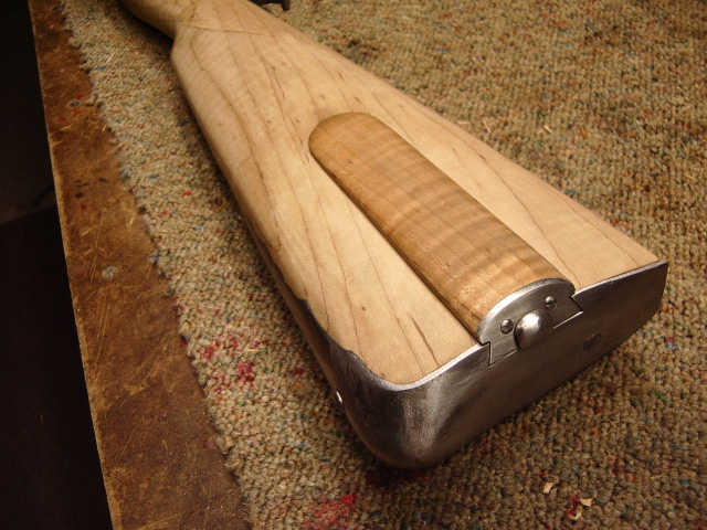
Now the patchbox lid is installed and a thumb recess needs to be made to make it easier to remove in the field.
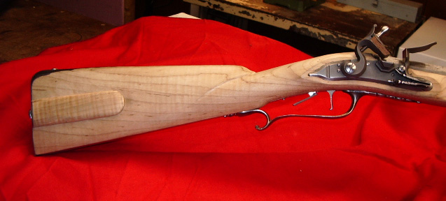
With the patchbox lid installed, now I will go back and start shaping the rest of the forearm area. See Shaping Stock.
Came back and wanted to remove the wood in the patchbox cavity. The following two photos shows my progress.
I
drew an 1/8" line around the perimeter, except at the rear, I left a
1/4" of wood to the buttplate. Then I used a 1" bit Forester  bit
to drill a series of holes into the stock. I drilled to
bit
to drill a series of holes into the stock. I drilled to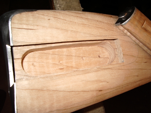 a depth of approximately 5/8" deep. Using my chisels, I then took out the
remaining wood to the lines. This left me with a cavity measuring 4" long,
1" wide and 5/8" deep.
a depth of approximately 5/8" deep. Using my chisels, I then took out the
remaining wood to the lines. This left me with a cavity measuring 4" long,
1" wide and 5/8" deep.
Hoot AL Rifle Shop
If you like the site or have any questions, drop me a line by clicking on "Hoot" below.

(c) Copyright 2005. All Rights Reserved.