Install Trigger Guard: (Discovered new challenge!)
This proved to be an interesting project in itself, as you will see below.
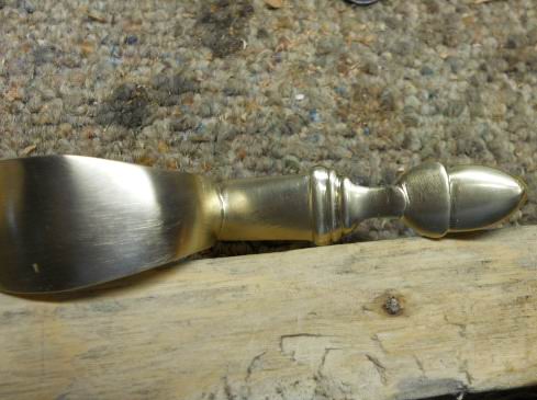
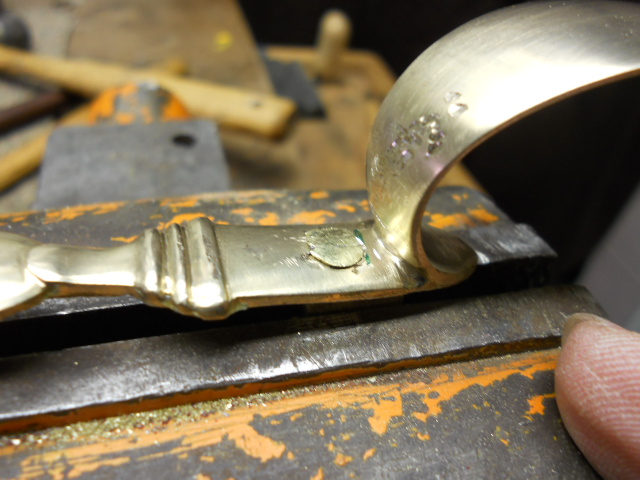
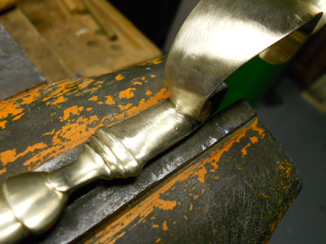
The first thing I like to do is to polish the trigger guard. In the photos you can see how much they need to be cleaned up. To do this I cut out a piece of pine to the shape of the guard and then epoxy it to the wood. This holds the guard securely in the vise for polishing with needle files and various grades of sand paper.
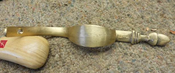
Now you can see the finished product. To remove the guard from the wood, apply heat via a torch to heat the metal and this allows the guard to be removed from the wood.
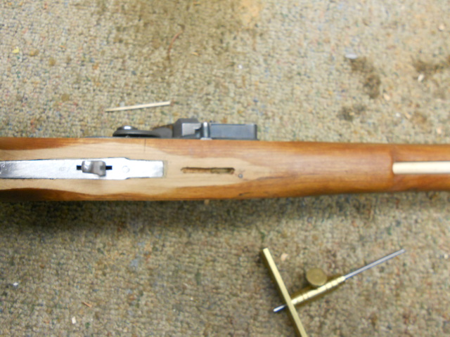
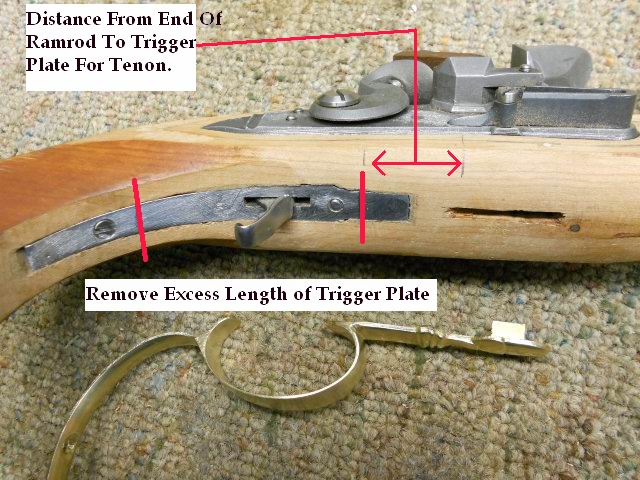
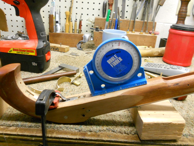
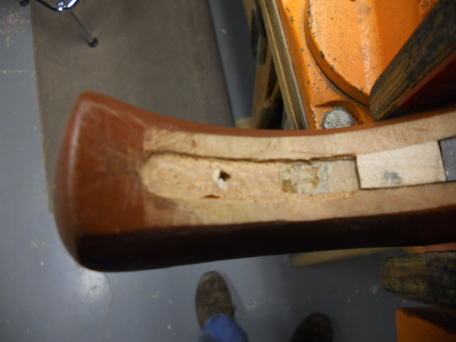
When I checked the depth of the forward tang on the guard, I discovered the tang passed into the ramrod channel this inhibited the ramrod from seating. I dropped a dowel into the ramrod channel to check the depth. Then marked this on the outside of the stock. I noticed the trigger plate was too long
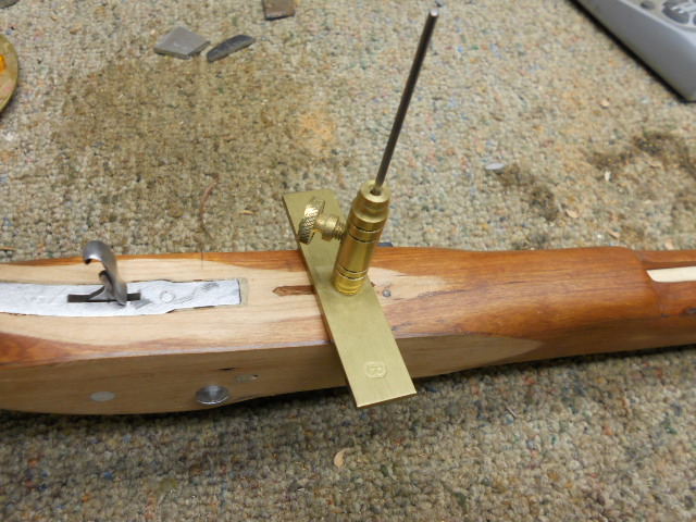
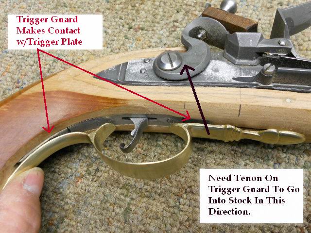
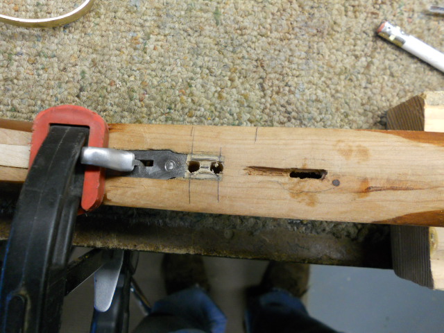
Holding the trigger guard up to the stock indicated the guard made contact with the plate in two places. I then cut the plate down to remove this interference. At this point, I inlayed wood to fill in the cavities.
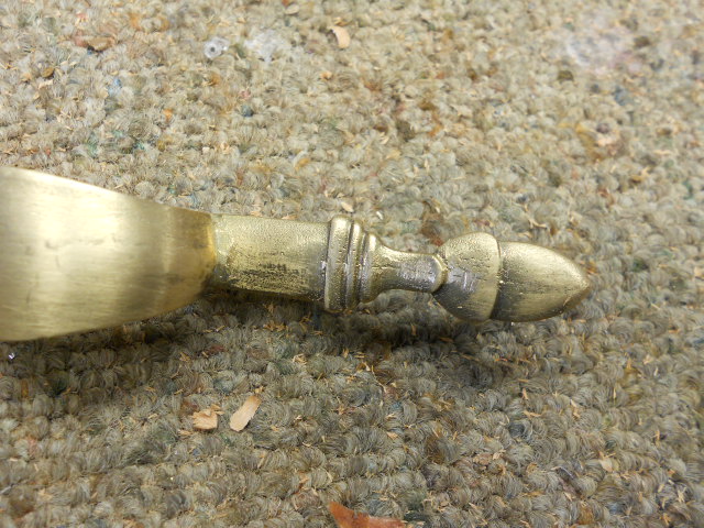
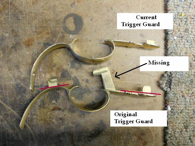
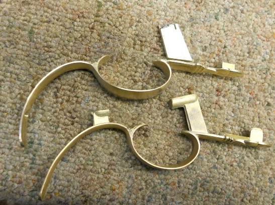
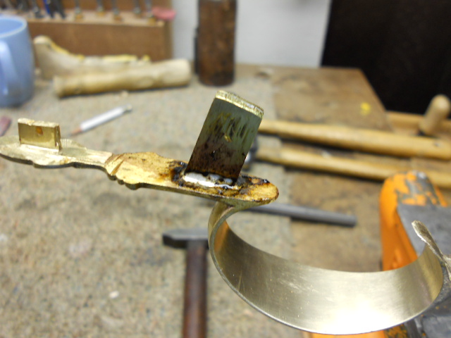
When I compared the current trigger guard with the other trigger guard in the other kit, I discovered my friend had cut off the tenon I needed inorder to properly inlet the guard into the stock behind the end of the ramrod. You can see this in the photo. The front tang should have been removed and not the large tang.
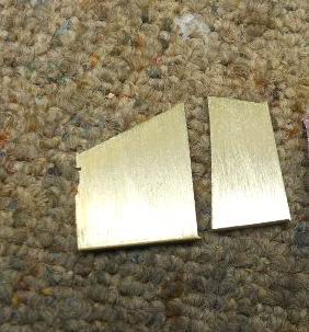
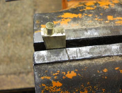
To remedy this, I have to make a new tang with the same thickness as the original tang. I took two pieces of 1/8" brass scrap pieces and soldered them together. Then I cut out the tang to match the 20 degree angle like the original tang.
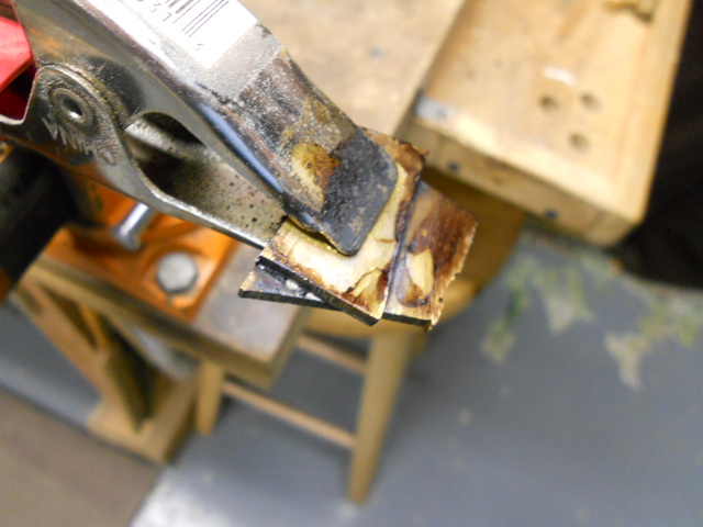
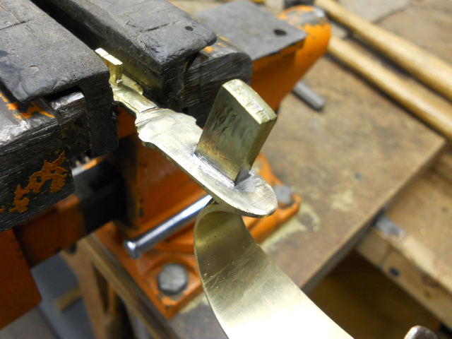
To mount the new tang, I will need to rivet the tang to the trigger guard. First I cut away material on the mounting surface of the tang. Next I rounded the exposed material. To strengthen the tang, I drilled a hole, counersunk the holes and riveted a brass rod thru the tang.
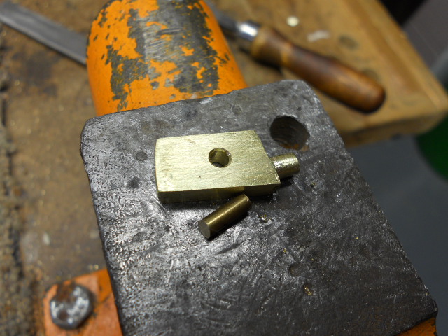
Below, you can see the process. Note, both sides of the tang were riveted. Measuring the size of the rounded tab, I drilled a hole into the trigger guard and riveted the new tang on to the trigger guard.
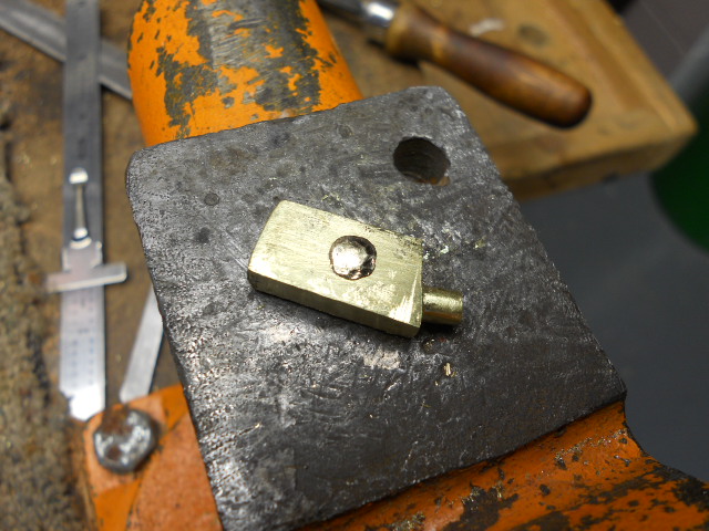
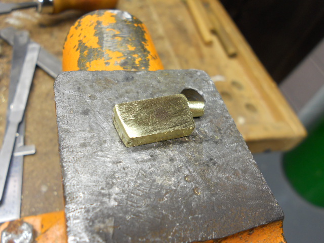
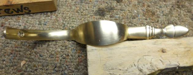
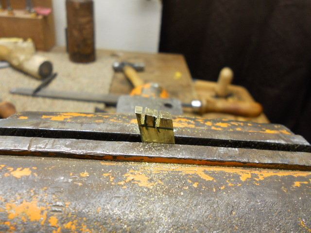
Once it was riveted the excess material was filed away and polished. To further secure the tang to the guard, the tang was soldered with silver solder.
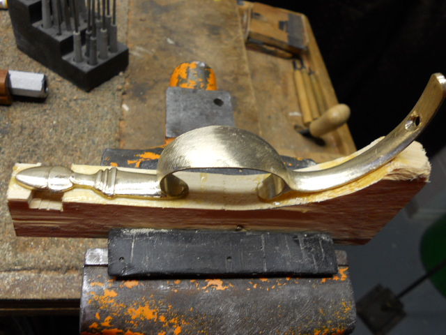
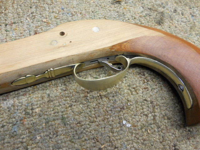
Now we have a correct trigger guard. The pistol stock was elevated to a 20 degree angle, so when the holes are drilled to inlet the trigger tang into the stock, it can be done at a 90 degree angle. Two holes were drilled and excess material was removed with chisels. The trigger guard tang was blackened and slowly inletted into the stock. Once the guard was flat to the stock, the forward end of the guard was fully inletted into the stock.
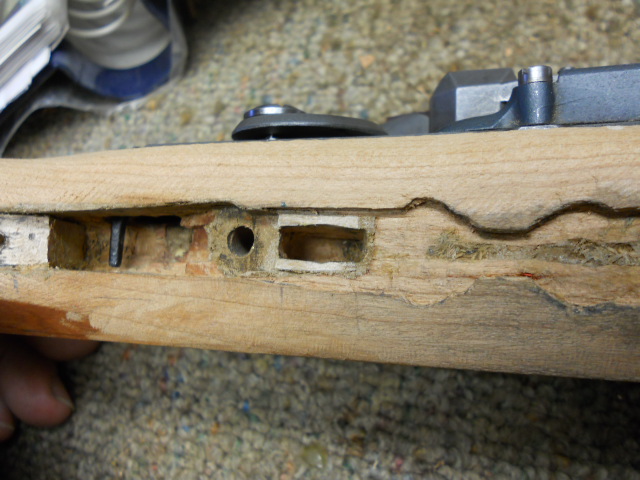
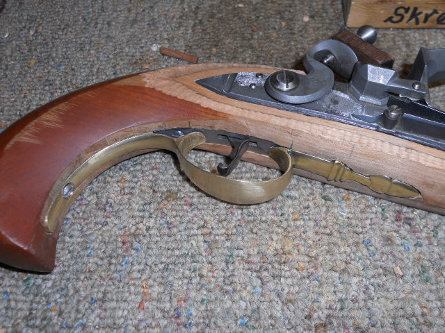
With the forward part of the guard fully inletted into the stock, it was clamped and I used a 1/16" drill bit to drill a hole thru the stock inside of the lock cavity, thru the tang and out the other side of the stock. This way, the pin can be removed once in place to hold the trigger guard.
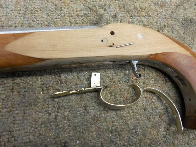
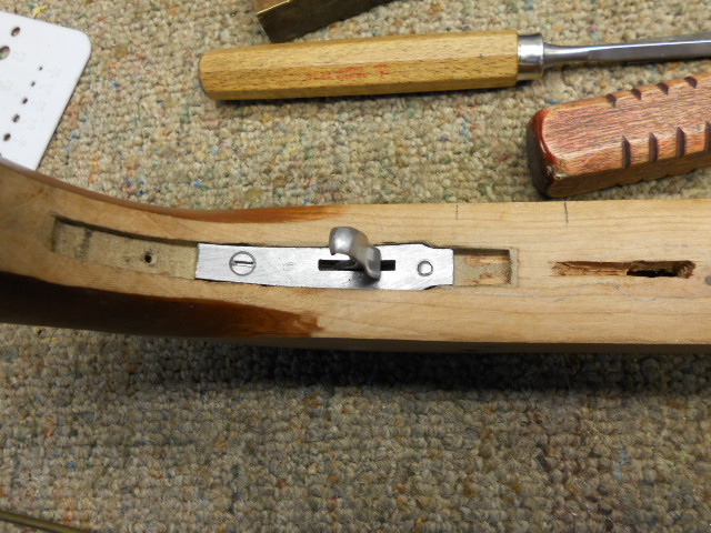
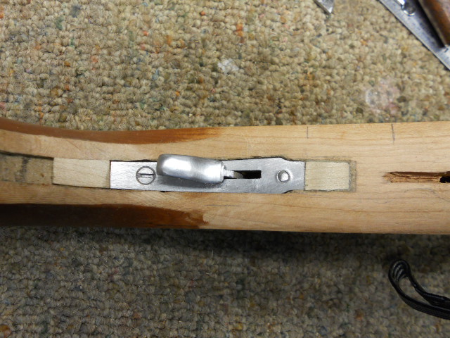
Prior to inletting the rear portion of the trigger guard, I had to plug the hole for the previous screw which was used. The new location of the trigger guard required a new location for screw placement. This portion of the guard was reinletted flush with the stock. As you can see below, the guard is now installed.
Hoot AL Rifle Shop
If you like the site or have any questions, drop me a line by clicking on "Hoot" below.

(c) Copyright 2005. All Rights Reserved.