Building and installing the patchbox:
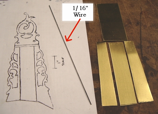
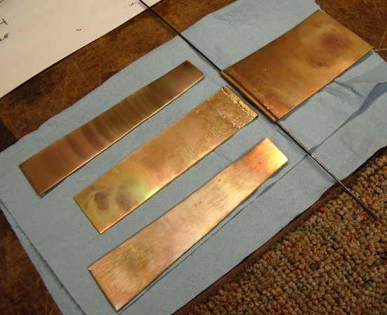
First step was to cut out the brass to match the trace pattern I was provided of the original. I used .054" thick brass. Same brass used for door kicker panels. It is same thickness as the store bought patchboxes.
 I
also will be using a 1/16" wire for the hinge.
I
also will be using a 1/16" wire for the hinge.
I started with the patchbox lid. I folded over the end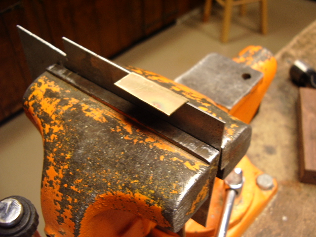 of the lid 3/8" from the end and formed a 90 degree angle. Then I placed
this up against a 1/16" thick piece of metal.
of the lid 3/8" from the end and formed a 90 degree angle. Then I placed
this up against a 1/16" thick piece of metal.
Using a wooden block to support the backside, I then tapped the brass down
over the steel to form a loop in the brass.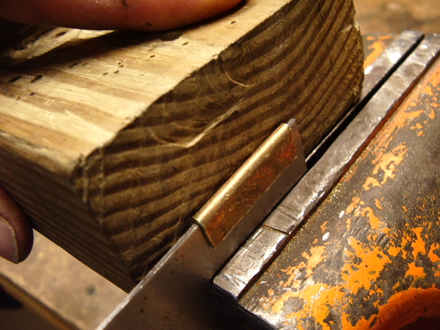
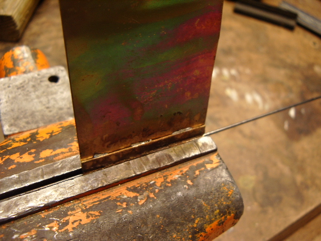
Then I placed the brass into the vise and dropped the 16" wire into the
looped end of the brass. 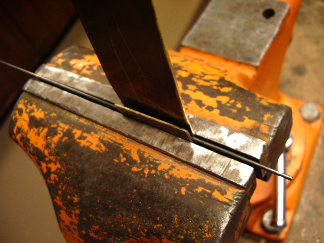
Next I used a flat bladed screw driver and a hammer to tap along the two
opposite sides to push the metal toward the wire. This shaped the brass to form
a tight loop over the wire.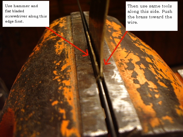
Once this was done, I flipped the lid to have the hinge above the vise. Now I
wanted to center the hinged portion with the lid. To do this, I used a block of
wood and a hammer to tap from either side till the wire aligned with the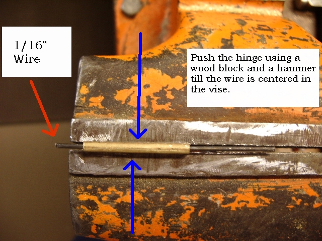 center of the opening between the jaws of the vise.
Once satisfied, I soldered the flaps down to secure them in position.
I repeated this process for the finial portion of the lid.
Now I made a center mark on both the lid and the finial. According to the
photo it appeared the lid was cut back about 1/4" from either side. So I
made same measurements and marked the lid. Here is a photo of the proposed
knuckle I will make. 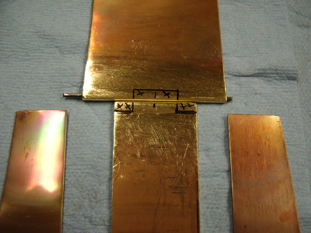
I cut out the knuckle on the lid first. 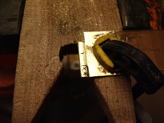
Then I again used the two center marks on the two pieces to align them up again.
Now using a knife, I used it to trace marks onto the final with the lid laid
over the hinge portion on the finial. 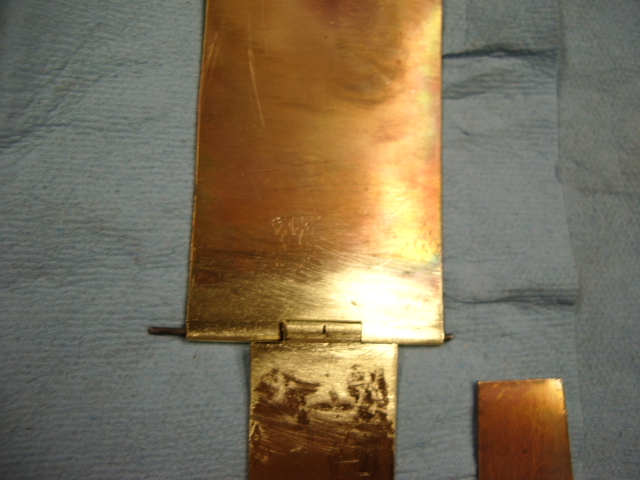
I cut out the hinge portion on the finial. By cutting on the inside of the
lines, I could file the opening to match the lid knuckle. Once the wire was able
to pass thru both pieces easily, I beveled back the undersides of the
knuckle for when it will be bent to fit the profile of the stock later. 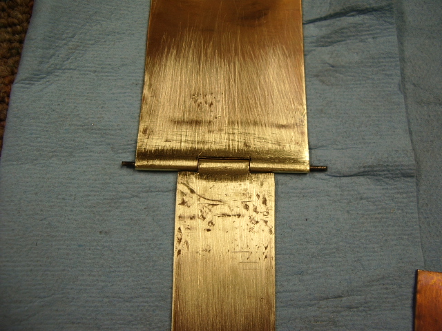
Now I was ready to cut out the patterns and glue them
to the brass pieces. 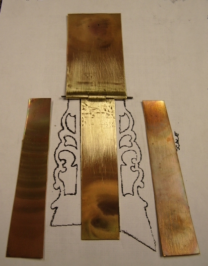
Once the patterns were glued to the brass, I wrapped the brass with patterns attached with two layers of clear 2" wide packaging tape. This helps hold the pattern in place and the tape works like a lubricate for the jewelers saw when cutting.
Here I have cut out the openings in the patchbox and my next step it to cut
out the outside edges of the finials. 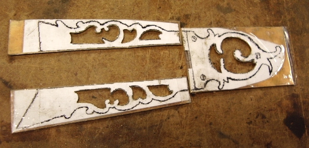
Almost there. Note, I left excess metal along the ends so I can fit this patchbox to the buttplate on this rifle.
Now the patchbox is fully cut out. 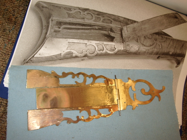 Here
you can see a comparison between the original and the new patchbox.
Here
you can see a comparison between the original and the new patchbox.
Here it is shaped for laying on the buttstock of the rifle.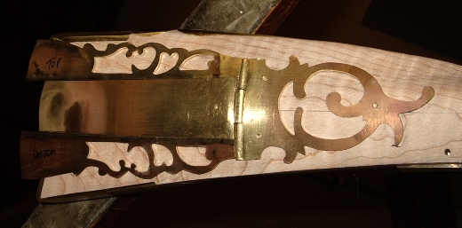 You can see the pencil line indicating the center line running from the wrist to
the buttplate.
You can see the pencil line indicating the center line running from the wrist to
the buttplate.
Three 1/16" holes were placed for the screws in the finial and then
several small pin holes were drilled for the brass nails to be used later.
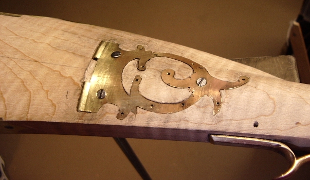
The finial hinge was inlet into the stock first. This allowed the finial to lay
flat against the stock. Then 1/16" drill bit was drilled thru the three
screw holes into the stock. Clearance holes made for the screws and the
holes were beveled. The 1/16" holes drilled earlier in the stock now
serve as pilot holes for the #4 screws to hold the finial to the stock. 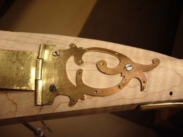
Now I will be inletting the finial into the stock.
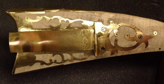
Once this is done, the lid is reattached to the finial and the lid is
inletted into the stock without the buttplate removed. I reinstalled the
buttplate prior to taking the photo. It will come off again when I install
the side finial. 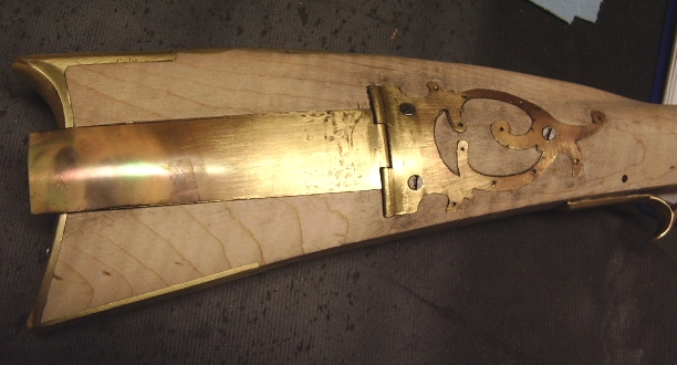
Note all the little dots are where I will be drilling holes for the steel
nails I will be using to secure to the stock. 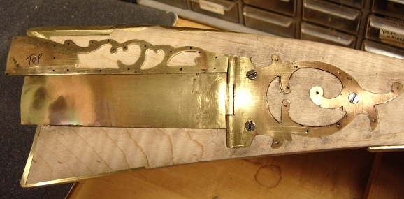
I drilled holes in same locations on the side panel as the original. Then I
tacked in a few nails to hold it in position for inlaying. Then proceeded to
remove the wood and then inlet the top panel into the stock. Here is the
panel inlet with the steel brad heads exposed. 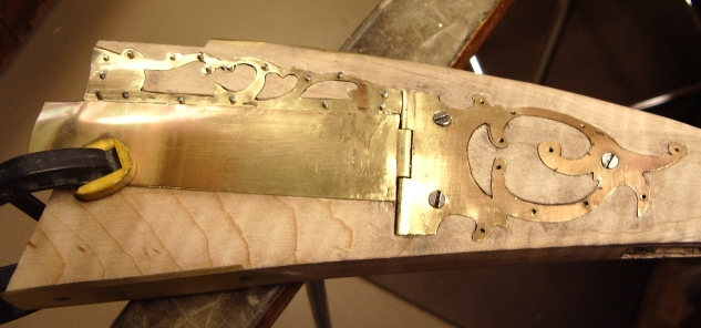
Here is the lower panel with the steel brads holding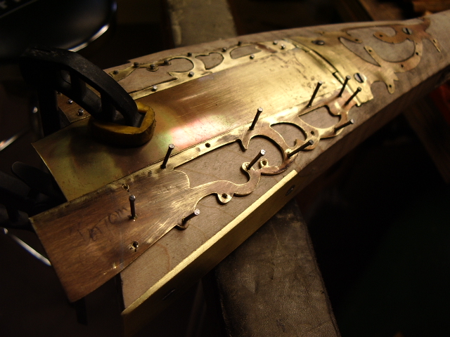 the piece so I can cut out the wood for inletting.
After this was inletted, I then filed down the brad heads slowly to fill the countersunk nail holes in the side panels. Still have a lot of work to do to finish them. So I will work on that later and started to lower the patchbox lid into the buttplate by filing the buttplate.
 Once the lid edges were flush with the side finials and into the lid, I lifted
the lid and removed the wood in the patchbox cavity. Using a 7/8"
auger bit, I bored down only 3/4" into the stock.
Once the lid edges were flush with the side finials and into the lid, I lifted
the lid and removed the wood in the patchbox cavity. Using a 7/8"
auger bit, I bored down only 3/4" into the stock. 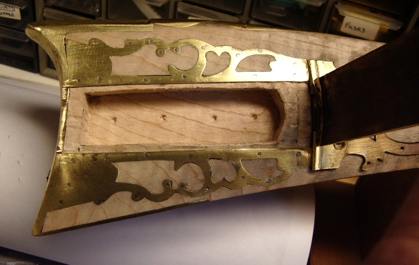
Now I needed to make the opening mechanism spring for the lid release. The
exposed end of the latch had a square button and the rest of the latch was flat
spring steel. So I found a piece of steel and shaped a piece of spring
steel into the rough shape of the mechanism, then laid then down to check for
length.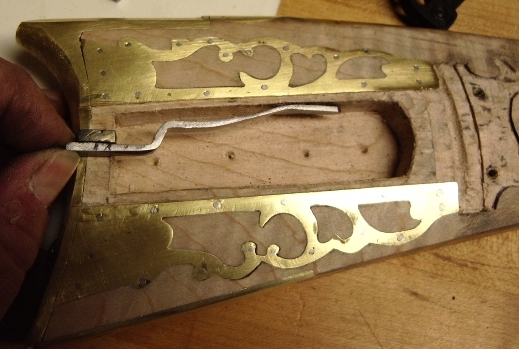
To fit the steel button onto the spring, I tapped the end o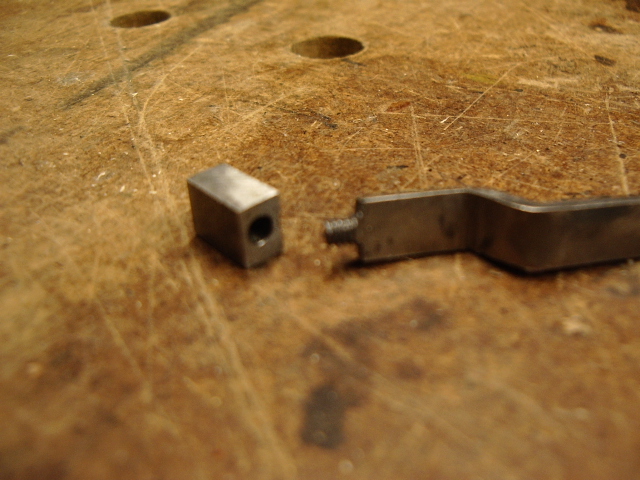 f
the spring to 5-40 threads and the same for the button.
f
the spring to 5-40 threads and the same for the button.
Here is a photo showing the assembly prior to positioning and tempering the
steel. 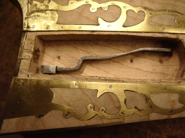
Here the mechanism is installed with excess button exposed thru the
buttplate. Note I used two #4 screws to secure it as opposed the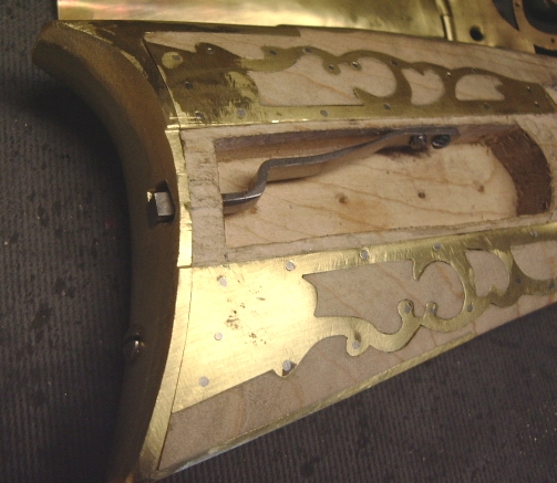 single nail on the original. I was informed by the owner, the mechanism
has worked loose over time. The screws should prevent this.
single nail on the original. I was informed by the owner, the mechanism
has worked loose over time. The screws should prevent this.
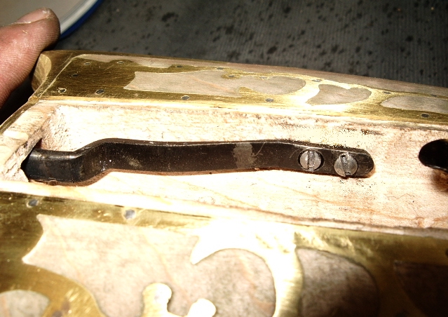
Here the spring has been tempered and the mounting screws. I will take down the heads for appearance reasons, later.
I took a scrap piece of 1/16" steel. Cut down and exposed a
1/8" tall stub on one end of the steel. This left me a shoulder on either
side of the stub. Then I slightly rounded the stub. Drilled a 7/64"
hole into the lid. The location of the hole was center over the top of the
latch spring in the area for the spring to latch onto the mechanism. 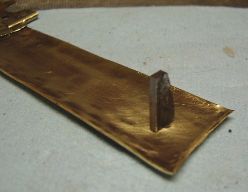
 Then
I clamped the steel into a vise and peened the steel into the lid. I made
sure the steel was perpendicular to the sides of the lid.
Then
I clamped the steel into a vise and peened the steel into the lid. I made
sure the steel was perpendicular to the sides of the lid.
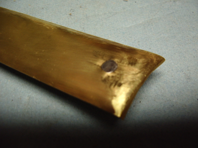
Then I soldered the steel onto the lid. This will prevent it from rotating
later. Here you can see I started shaping the latch to compensate for it to wrap
around the latch mechanism. I had purposely rounded the surface side of
the latch which will have the latch rubbing against it. So I concaved the side
of the latch to fit it. Note, the latch hook at the bottom was purposely
left short, so I could file it down later till I had a tight
"snap-fit" of the lid to the stock. 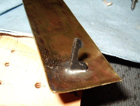
With a lot of closing motions and filings of the latch hook, the lid finally
"snapped" into the box. I pounded down the exposed end of the
lid, it you had not noticed earlier. 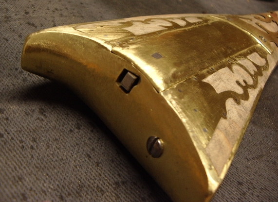
Next I then beveled the edges of the button, similar to the original. With
the small relieved area below the button, releasing the latch by pushing up on
the button is a lot easier. 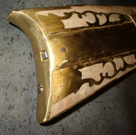
Here is a movie showing the button being pressed upward and the lid opening. Note, it is a 3.5 MB file. MOVIE
Hoot AL Rifle Shop
If you like the site or have any questions, drop me a line by clicking on "Hoot" below.

(c)
Copyright 2005. All Rights Reserved.